
It is important to create new solids or a multi-lump part file. STEP #9: I will now create new extrusion solids for the rest of the frame members and set their extrusion depth to be equal to FThk. STEP #8: Next we need to share sketch #2 in order to extrude the other frame pieces/outlines. However, I’ll select one and extrude it by setting its extrusion distance to a controlling factor of FThk=0.250. STEP #7: At this point it doesn’t matter which profile you use for the extrude step. STEP #6: Now I will exit the sketch and turn the visibility off on the first sketch (sketch #1) to ensure we are selecting the correct profile when we extrude our frame pieces in the next step. I am only doing this so the individual pieces could be welded together later on in the fabrication process. STEP #5: Next I will add the lines to represent the miters or cuts on the ends of the frame pieces.

25 in didn’t appear correctly in the sketch compared to the overall size of the workstation, so I updated it to 1 in. For the first controlling dimension of my workstation, I want to create a parameter that allows me to control the frame width based on the design of the workstation.įrom there I will dimension the rest of the frame width to be equal to this dimension/parameter.Īfter finalizing the frame outline I realized a frame width of. STEP #4: Now I will offset the projected geometry to make the inner frame geometry. I will now start another sketch on the same plane as sketch #1 and project all the entities from that first sketch. STEP #3: Next we need to create the inner lines that make up the frame that will support the top of the workstation. STEP #2: Define the sketch (sketch #1) as being adaptive by right mouse clicking on it in the browser and selecting “adaptive”. So ask yourself, if you did show all “degrees of freedom” for your sketch, are you able to change the configuration without any problems? Once this outline is complete, I will remove all of the temporary dimensions since we will be controlling it later on.

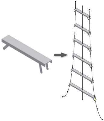
Too many constraints may hinder you and not having enough could produce incorrect results. The other thing you have to consider when working with an iCopy model is how the sketch is constrained. However, I would recommend creating this sketch away from the origin point and also place some temporary dimensions on your sketch to get a close representation of your design. The size and location of this sketch is not crucial since the iCopy tool will be doing most of the work. This part will be considered as the Skeleton Layout Part. STEP #1: Start a new part and draw (sketch) a skeleton that represents the outline of the workstation top. So let’s get started and a take a look at how iCopy can assist us. Outside of iCopy I could use frame generator, iAssembly, iLogic or maybe a couple of other Inventor tools to accomplish my end results. Although there are numerous things you have to consider when designing a workstation, today I will only focus on a simple frame design that supports the top surface of the workstation. Let’s say my company designs L-shaped CAD or lab workstations and we offer them in standard and custom sizes. I believe more users could benefit from seeing this workflow instead of demonstrating how iCopy can be used to design a cell phone or electrical tower. However, for today I want to share the other workflow that iCopy can be used for. So ask yourself, if you had to model this type of structures in Inventor, would you want to model every cross member and then assembly them to your model? Probably not… So that’s one workflow that iCopy can simplify for you. But as the tower width changes the length of these members are changing as well. Images from Google/īased on these images, the supporting cross member configuration looks the same as the tower goes vertically. iCopy is a tool that helps streamline two types of workflows when you’re designing components in an assembly that look the same but are changing (example: width, length, and etc).įor example, take a look at a high power electrical or cell phone tower.

“iCopy” was a feature that was part of the Inventor 2011 release and for Inventor 2010 it was downloaded through Autodesk Labs. Posted on November 23, 2015 by Product Support Specialist, Mark LancasterĪ while back while trying to determine when a certain function was added to Inventor, I came across a reference to Inventor iCopy.


 0 kommentar(er)
